
Digital Control of a Robotic Arm
Digital Control of a Robotic Arm
It is in ECE3111 (Systems Analysis) and ECE4121 (Digital Control Systems) that Electrical Engineering students first become exposed to the challenges of creating a stable control system. During the Fall 2019 semester in ECE4121, the five students in the class, Evan Faulkner, John Kaminski, Daniel Osborn, Ben Rattet, and Zacharya Samih, faced those challenges head on as they took it upon themselves to control a robotic arm to behave as a gantry to stabilize a non-inverted pendulum attached to the arm. The controller’s objective was to have the angle of the pendulum reach zero as quickly as possible. Prof. Krishna Pattipati, who was the class instructor, and graduate students, Adam Bienkowski and James Wilson, helped the students with the project.
The robotic arm used for this project was given to one of the group members by a faculty member at E. O. Smith High School. 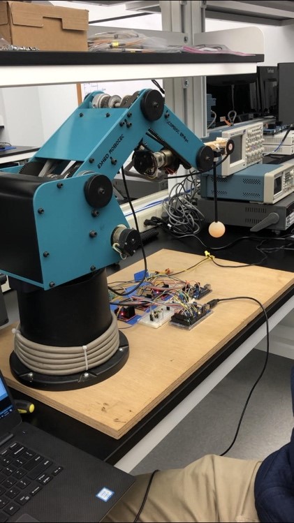 It was first purchased in 1996 and was no longer being used by the school. It was equipped with three quadrature encoders for sensors and brushed DC motors to control the arm’s movement. However, since this arm was no longer in use, it did not come with a datasheet. As a result, the group was unable to model the system using physics-based models, since the parameters of the arm were unknown. Therefore, the group decided to use a system identification approach to derive the state space model of the system.
There were already controllers in place that would move the arm to a given set point, but the team needed to design an outer-loop controller that would determine the optimal set point. Therefore, the system needed to be modelled with the set point as the input, and the angle of the pendulum as the output. The states of this system would be the position of the two joints in the arm, the angle, and each of their derivatives. To derive a discrete state space model, the arm was subjected to a staircase waveform of set points as an input, and the states were measured at each time step. Consequently, the group obtained the six states, the input, and the states at the next time step. 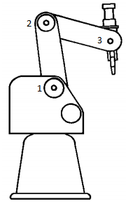 A Python program was written to train the state space model using a library from Scikit-Learn. The model returned a discrete state space representation of the system, which was then used to design two controllers.
The first was a PD controller coupled with a PI controller. The PD controller regulated the angle of the pendulum to zero, while the PI controller was used to return the robot arm to the desired set point. The PI controller had much smaller gains than the PD controller; therefore, the arm would only move back to the center after the pendulum stopped. This controller successfully regulated the angle of the pendulum to zero; however, it was very slow when the pendulum excursions were large.
The second controller was a linear quadratic regulator (LQR) controller. The group determined the state and control weights Q and R, and then found the gain vector using MATLAB. This controller was also able to regulate the angle of the pendulum to zero, if the initial offset of the pendulum was sufficiently small; however, there were multiple problems with this controller. In all of the data used for training, the angle of the pendulum was relatively small; therefore, the LQR controller would shake when the angle of the pendulum was too high.
To combat the large angle excursion issues associated with the PID and LQR controllers, the group proposed the implementation of a hybrid “Bang Bang” and PID/LQR controller. This controller employs the “Bang-Bang” controller until the system reaches a point where linear control can be used. If the angle of the pendulum was outside of a specified threshold, the set point of the robotic arm was set to the either of the edges of the experimental track, until the angle was back within the region where linear control could be used. Once linear control could be used, the PID or the LQR controllers would be turned back on. This implementation caused the PID and the LQR controller to both speed up and effectively settle the pendulum to its center position, no matter what the initial offset was.
Categories: News
Published: September 18, 2020
Available Archives
